
Standards & Protocols, Part 1
The OSI model
Section titled “The OSI model”Open Systems Interconnection (OSI) comes from the International Organization for Standardization (ISO). It is a common reference for how interconnection standards get written: seven abstract layers describing communication from physical bits on the medium up to a distributed application.
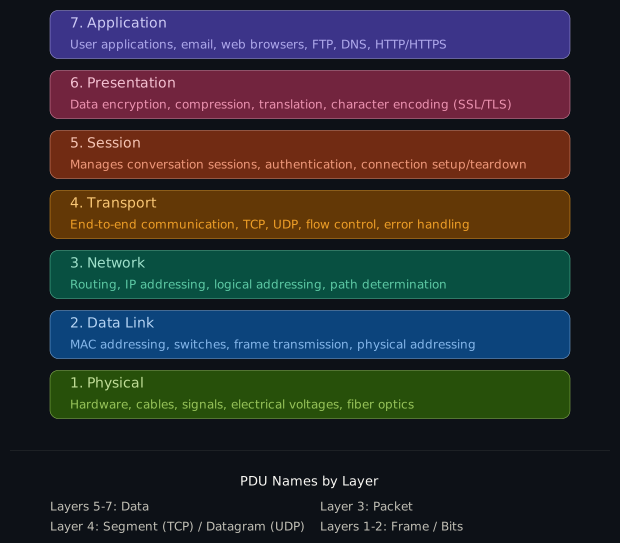
The model is simply a teaching abstraction, and is not something any real stack implements. Working systems follow TCP/IP, which collapses layers 5, 6, and 7 into one application layer. However, when someone mentions “Layer 2,” this is what they mean.
For the rest of this lecture we’ll be narrowing in on Layer 2.
Layer 2: data link
Section titled “Layer 2: data link”Layer 2 moves data across a single link between two directly connected nodes. If Layer 1 is the road, Layer 2 is the car that drives on it. It splits into two sublayers:
- Logical Link Control (LLC) identifies the Layer 3 protocol inside the frame. In practice that is the only thing it does, and it shows up as the LLC/SNAP header on a Wi-Fi frame.
- Media Access Control (MAC) decides who may transmit, and defines the frame structure.
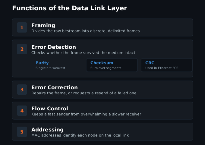
Flow control is one of the items not covered here. In practice, this is abstracted to higher layers.
Framing
Section titled “Framing”Anatomy of an Ethernet frame (IEEE 802.3)
Section titled “Anatomy of an Ethernet frame (IEEE 802.3)”How Layer 2 wraps a Layer 3 packet for delivery across one link:
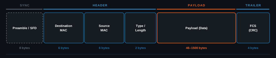
- Preamble: 7 bytes, letting the receiver lock onto the signal and know a
frame is coming. The SFD (start frame delimiter) is 1 byte set to
10101011, marking where the frame itself begins. - Addressing: destination and source MAC addresses identify the NICs on the local segment.
- Type / Length: a value of 1500 or below is a length
- Payload: carries the Layer 3 packet handed down, so the IP header and its data when IP is in use. Padded up to 46 bytes if it is shorter.
- Error check: the frame check sequence holds a CRC-32 over the header and payload. It is not a cryptographic hash, just an error check, and the receiver drops any frame that fails it.
A MAC address is 48 bits, six hex bytes. The first three are the OUI, assigned
to the manufacturer by the IEEE, and the last three are the vendor’s own device
number. Two bits in the first byte matter: the lowest bit marks a group
(multicast) address, and the next one up marks a locally administered address,
which is what a phone sets when it randomizes its MAC. FF:FF:FF:FF:FF:FF is
broadcast.
Carrier Sense Multiple Access
Section titled “Carrier Sense Multiple Access”CSMA is a MAC-layer scheme for sharing one channel among many stations. Wireless devices cannot detect a collision while transmitting, so CSMA/CA avoids one instead. Stations sense the channel and wait a random backoff before sending, which makes collisions less likely, though two stations whose backoff expires in the same slot will still collide.
- Collision Avoidance (CSMA/CA) keeps collisions from happening, and is used on wireless links
- Collision Detection (CSMA/CD) spots a collision during transmission and aborts. Wired half-duplex Ethernet only.
- Request-to-Send / Clear-to-Send (RTS/CTS) is optional, and off by default on most gear
A radio needs CSMA because it cannot hear a collision while it is transmitting, radio time costs power, and interference is everywhere.
- Pros: efficient, simple, flexible, and cheap
- Cons: scales poorly, adds delay, guarantees no delivery, and is easy to jam
Features
- Carrier sensing: stations listen to the channel before transmitting
- Collision avoidance: a random backoff prevents overlaps
- Acknowledgements: the receiver confirms every unicast frame it accepts. Broadcast and multicast go unacknowledged.
- Fairness: no one station can monopolize the channel
- Binary exponential backoff: the contention window doubles after each failed attempt
Strategies used
- Interframe Space (IFS): a fixed idle gap after the channel clears, so replies get priority
- Contention window: each station waits a random number of time slots
- Acknowledgements: no ACK inside the timeout means the sender retransmits
Anatomy of a Wi-Fi frame (IEEE 802.11)
Section titled “Anatomy of a Wi-Fi frame (IEEE 802.11)”How Layer 2 wraps a Layer 3 packet when the link is a shared radio channel.
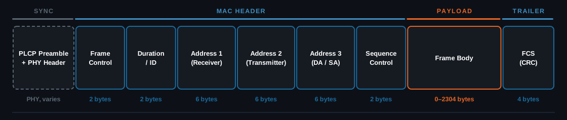
The sync section is PHY, not part of the MAC frame.
- Frame Control is the dense one: protocol version, type (management, control, data), subtype (beacon, RTS, CTS, ACK, QoS data), plus the Retry, Power Management, and Protected Frame flags.
- Addressing: the ToDS and FromDS bits set what each address field means. DS is the distribution system, the network behind the APs, usually wired Ethernet. Both bits set means AP to AP, which is the mesh and WDS case, and the one that adds a fourth address. Ethernet needs only two addresses because it has one hop; Wi-Fi needs a third because the AP is a relay, so the frame carries both the hop addresses and the end-to-end addresses.
- Duration tells every station that hears the frame how long to stay off the air. This is the field that sets the NAV.
- Sequence Control is 12 bits of sequence number plus 4 of fragment number. It exists because a lost ACK makes the sender retransmit a frame the receiver already accepted. The number does not change on a retransmit, so the receiver spots the duplicate and drops it.
- Frame body opens with an 8-byte LLC/SNAP header. The payload is encrypted under WPA2/3.
- Error check: the same CRC-32 as Ethernet, over the MAC header and body.
Error detection
Section titled “Error detection”Types of errors
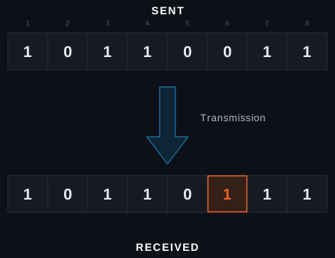
Section titled “Types of errors”A single-bit error alters only one bit of the transmitted data.
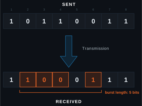
A burst error corrupts two or more bits in one span, counted from the first bad bit to the last.
Three techniques, one pattern
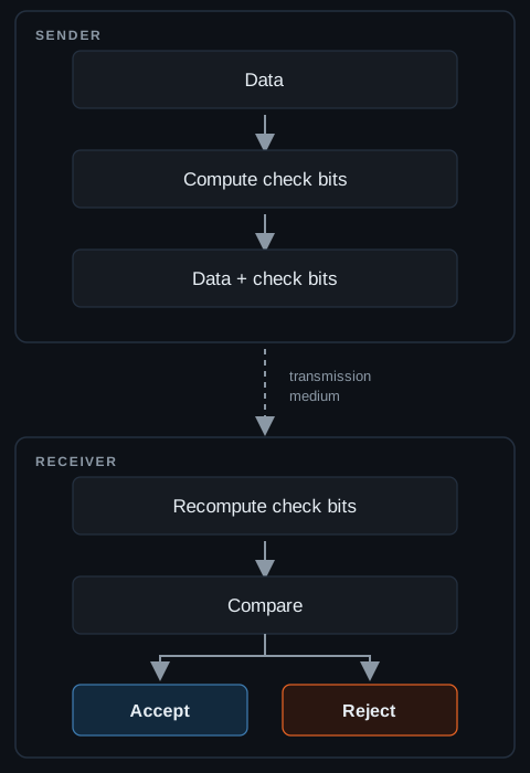
Section titled “Three techniques, one pattern”- Parity checks: one extra bit, set so the number of 1s comes out even or odd
- Checksum: a calculated sum over the data, recomputed and compared at the far end
- Cyclic redundancy check (CRC): polynomial division of the data, with the remainder carried as the check value
All three follow the same three steps:
Simple parity check
Section titled “Simple parity check”- Parity bit: one extra bit appended to the data
- Even or odd: both ends agree in advance which the total must be
- Sender: counts the 1s and sets the parity bit to match
- Receiver: recounts, then accepts, or discards and asks for a retransmit
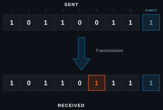
It catches every single-bit and odd-numbered error and is trivial to implement. It is blind to even-numbered errors, and weak on noisy channels.
Longitudinal redundancy check
Section titled “Longitudinal redundancy check”Also called 2-D parity. Lay the data out as rows of one byte, XOR each column (an even number of 1s gives 0, odd gives 1), and append the result to the end of the packet.
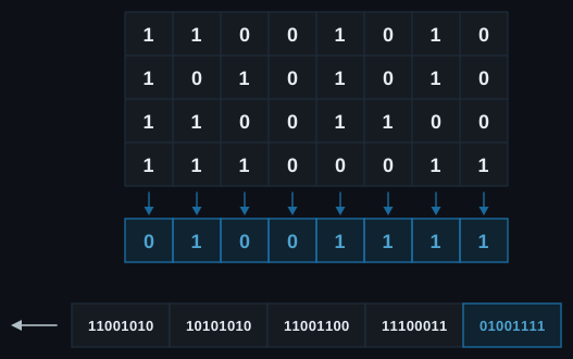
The advantage is that it detects burst errors. The disadvantage is that it is blind to two bits flipped in the same column of two different rows, because they cancel.
Checksum
Section titled “Checksum”The sender splits the data into fixed-size segments and adds them in 1’s complement, then takes the complement of that sum as the checksum and sends it with the data. The receiver repeats the addition, and an all-ones sum means accept.
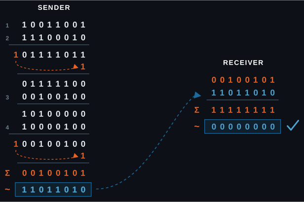
Note that a 1’s complement is not the same as adding 1. It is a bitwise inversion, with the carry out of the top wrapped back around into the bottom.
Checksums are widely used in IPv4, TCP, and UDP. They are fast to compute and easy to implement, but less reliable than a CRC, because errors can cancel out.
Cyclic redundancy check
Section titled “Cyclic redundancy check”CRC check bits are appended so the frame divides evenly by an agreed polynomial. The receiver divides by the same polynomial, and a zero remainder accepts while a non-zero remainder means error.
Take data 1101 and generator 1011, which is x³ + x + 1. The generator is
degree 3, so three zeros are appended, four XOR steps follow, and the remainder
001 is the CRC.
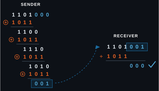
The division sign here means repeated XOR, not arithmetic division. The receiver takes the original data with the CRC appended and divides it the same way.
CRC catches every single-bit and odd-weight error, plus any burst up to the CRC width, which is 32 bits on Ethernet. It is used widely in Ethernet and USB.
Error correction
Section titled “Error correction”Detection is not enough
Section titled “Detection is not enough”CRC and checksums tell a receiver that a frame is bad, but they cannot fix it. The only recourse is to ask the sender for it again, which
- On a slow or lossy link the round trip is expensive
- On a broadcast or one-way link there is nobody to ask, and live audio and telemetry cannot wait for it
Forward error correction
Section titled “Forward error correction”Send redundant bits alongside the data so the receiver repairs the damage itself. There is no round trip, so it works where a retransmit is impossible or too slow. The cost is bandwidth: every frame carries the overhead whether it is needed or not.
- XOR parity: send the XOR of N chunks. Any one missing chunk rebuilds from the rest, the same trick as LRC and RAID 5. It fills a known gap, not an unknown flip.
- Interleaving: scatter each codeword across the transmission, so a burst lands lightly on many codewords instead of destroying one
Hamming distance
Section titled “Hamming distance”Sources
Section titled “Sources”- Network Fundamentals (Network Academy)
- Ethernet Frame Format (GeeksforGeeks)
- Carrier Sense Multiple Access (CSMA) (GeeksforGeeks)
- IEEE 802.11 Architecture (GeeksforGeeks)
- Error Detection in Computer Networks (GeeksforGeeks)
- Longitudinal Redundancy Check (LRC) / 2-D Parity Check (GeeksforGeeks)
Diagrams on this page were made with Claude. Everything else is researched and written by club members.
Built with the help of Claude. All content is written and reviewed by club members.
Auburn University Mesh Club ·Source on GitHub